OSI LAYER MODEL BASED ON SCENARIO

OSI layer model for student :
This OSI Layer Model discussion
will begin with a Cobham Collage Campus network connecting to their private
network's Online Learning System Server via their home network (public IP
address) (Private IP Address).
Assume that the Cobham College
Campus network is attempting to upload a file to the Cobham College Online
Learning System. Let's start with the Application Layer, where data transit
services such as SMTP, POP3, and others are supplied to the file that a Cobham
Collage student wishes to submit into the Cobham Collage Online Learning System
platform.
The data is transported using the file transfer protocol (FTP) in this situation. On the Presentation Layer, the file will be converted to binary format, and file compression will begin in order to reduce the file's size. A 10MB file, will be compressed down to 5MB, allowing the content to be transferred even faster. Finally, it will encrypt the file delivered by the sender using SSL or another security protocol for data security concerns.
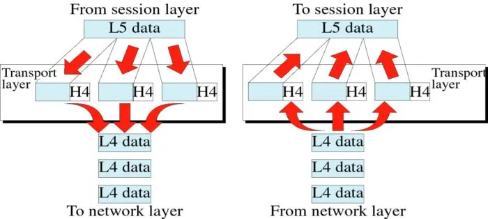
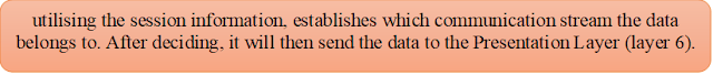
The data will subsequently be transmitted to the session layer, which will manage the communication session without interfering with the communicating systems' ability to communicate. The packet data unit for these three processes is data, which will be broken down into segments in the next phase. This transit layer is where the segmentation begins. Each segment contains the source and destination port numbers, as well as the sequence number. The port number's purpose is to get the data on the appropriate track, whereas the sequence number's goal is to reorder the out-of-order segments.
Furthermore, error control is an important part of this layer since it determines whether the segments have arrived and, if not, re-sends them. The two protocols employed in this operation are TCP and UDP. In our instance, TCP will be used to send the file since it assures that each data packet is transmitted and receives a message indicating whether or not the data has been received. Why didn't we utilise UDP instead of TCP? Because UDP is primarily used for video streaming, it does not reply to whether or not the data has been reached.
The network layer is the following layer, and it's here that the crucial parts of our data trip are influenced by the scenario due to communication between public and private IP addresses. This layer is responsible for delivering packets (PDU) from the original source (Sender) to the final destination (Receiver).
Logical addressing, which allocates an IPv4 destination to each segment, and routing, which handles packet delivery based on the IP address and subnet mask, are two procedures involved in this layer. Because of the public to private IP address, the routing will be different in this situation, with the sender (Public IP address) transmitting the data to the Cobham Collage Campus network main router (Public IP address), and then another routing within the Cobham Collage Private IP Address to transfer the data to the requested host. The data link layer is the next layer, where the hardware's MAC address is appended to the packet and the frame is created.
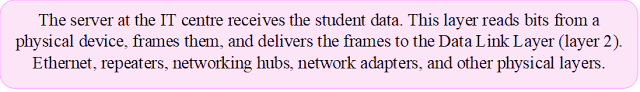
The objective of MAC is to maintain track of data packets as they go over a shared channel from one Network Interface Card (NIC) to another (Hop-to-Hop Delivery). Finally, the physical layer is in charge of moving bits from one layer to the next. In addition, the physical layer converts binary into a signal that can be transmitted over a medium. In this scenario, wireless and wired media are used.
Here the explanation based on OSI layer :
7. Application Layer

⬇
6.Presentation Layer

⬇
5.Session Layer

⬇
4.Transport Layer

⬇
3.Network Layer

⬇
2.Data Link Layer

⬇
1.Physical Layer

OSI Layer Model Server Side :
The student home modem at Cobham
College is now used for hop-hop delivery operations to the campus main network.
This approach will only go from layer 1 to layer 3, then from layer 4 to layer
7, if the destination source is reliable. We're going to start at the physical
layer and work our way up to the application layer to decode the file that a
student from Cobham College uploaded. Before moving on to the following layer,
data is first received via wired media on the physical layer.
Second, the frame is changed from
a frame to a packet at the data connection layer by removing the source and
destination MAC addresses. In the event that a network layer legitimate
destination is discovered, the logical address will be dropped (packet to
segments). If the destination is invalid, hop-to-hop delivery to the next node
is used. The transport layer's data (segment) checks sequence addressing to see
if any data were lost during transmission, and the layer's port addressing uses
error control methods to make sure the destination has been reached. No more
communication is allowed between the two participants after this layer, and a
new request to begin a new dialogue session must be made if more communication
is required.
The data will be restored to its
original format on the presentation layer, and it will be decrypted using the
same technique as on the transmitting side. The application layer will then
grant access to read, write, and view the file that a student from Cobham College
sent over a public network.
Here the explanation based on OSI layer :
1. Physical Layer

⬇
2. Data Link Layer


⬇
3. Network Layer


⬇
4. Transport Layer

⬇
5. Session Layer

⬇
6.Presentation Layer


⬇
7. Application Layer


Comments
Post a Comment